
10Gbps Fiber SFP+ Module | Single Mode Dual LC Transceiver | 10km | Cisco or Generic Switch Compatible
These Fiber SFP+ modules have been individually programmed to be compatible with Cisco Equipment and is 100% compatible with other generic sfp+ coding brands such as Tenda, Hikvision, TPLink, TrendNet, Netgear, Ubiquiti / Unifi, Cudy and generic OEM brands.
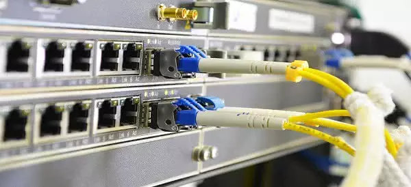
This SFP+ Module is Hot-Pluggable and it can be inserted into a Network or POE Network Switch without the need to power-down the switch.
Please see our guide at Fiber Optic Cables & SFP Compatibility for more information.
Product Features
- Up to 11.3Gbps Data Links
- Up to 10km transmission on SMF
- DFB Laser and PIN receiver
- Metal enclosure, for lower EMI
- 2-wire interface with integrated Digital Diagnostic monitoring
- Hot-pluggable SFP+ footprint
- Specifications compliant with SFF 8472
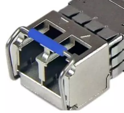
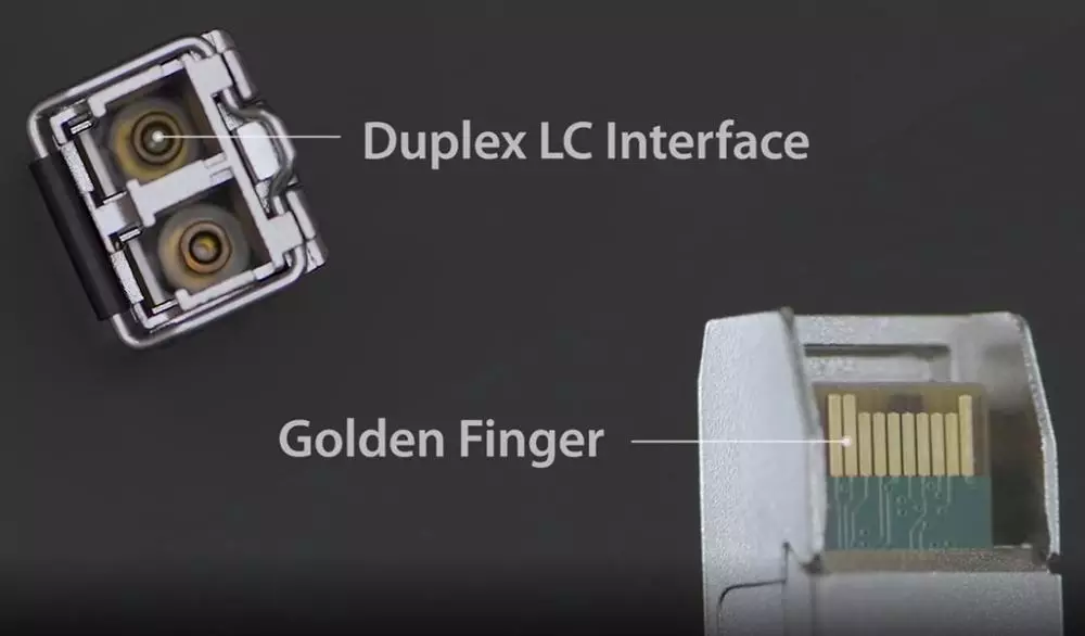
- Compliant with SFP+ MSA with LC receptacle
- Single 3.3V power supply
- Case operating temperature range:0°C to +70°C
- Power dissipation < 1.5 W
Applications
- 10GBASE-LR/LW Ethernet
- SONET OC-192&SDH STM-64
- OTN ITU-T G.709
- 10X Fibre Channel
- LTE systems
- Other Optical links
Example of Dual LC Fiber SFP Installation
Standard
- Compliant to SFF-8431
- Compliant to SFF-8472
- RoHS Compliant
Product Description
This SFP+ transceiver is designed for use in 10-Gigabit Ethernet links up to 10km over single mode fiber. The module consists of 1310 DFB Laser, InGaAs PIN and Preamplifier in a high-integrated optical sub-assembly. Digital diagnostics functions are available via a 2-wire serial interface, as specified in SFF8472. The module data link is RoHS Compliant.
These Dual LC SFP+ Modules are commonly installed with the Duplex Single Mode LC to LC Fiber Cables Below:
30M Duplex Single Mode UPC LC-LC Fiber Optic Cable | Fiber Patch Cord | Outdoor Drop Cable
100M Duplex Single Mode UPC LC-LC Fiber Optic Cable | Fiber Patch Cord | Outdoor Drop Cable
60M Duplex Single Mode UPC LC-LC Fiber Optic Cable | Fiber Patch Cord | Outdoor Drop Cable
150M Duplex Single Mode LC-LC UPC Fiber Cable | Fiber Drop Cable | Outdoor Cable
Absolute Maximum Ratings
| Parameter | Symbol | Min. | Typical | Max. | Unit |
| Storage Temperature | TS | -40 | +85 | °C | |
| Case Operating Temperature | TOP | 0 | +70 | °C | |
| Maximum Supply Voltage | Vcc | -0.5 | 4 | V | |
| Relative Humidity | RH | 0 | 85 | % |
Recommended Operating Conditions
| Parameter | Symbol | Min. | Typ. | Max. | Unit | Note |
| Case Operating Temperature | TOP | 0 | – | +70 | ºC | Without air flow |
| Power Supply Voltage | VCC | 3.14 | 3.3 | 3.47 | V | |
| Power Supply Current | ICC | – | 430 | mA | ||
| Data Rate | BR | 10.3125 | Gbps | |||
| Transmission Distance | TD | – | 10 | km | ||
| Coupled fiber | Single mode fiber | 9/125um SMF | ||||
Optical Characteristics
| Parameter | Symbol | Min. | Typical | Max. | Unit | Note |
| Transmitter | ||||||
| Center Wavelength | λt | 1290 | 1310 | 1330 | nm | |
| spectral width | △λ | 1 | nm | |||
| Average Optical Power | Pavg | -8.2 | +0.5 | dBm | 1 | |
| Optical Power OMA | Poma | -5.2 | dBm | |||
| Laser Off Power | Poff | -30 | dBm | |||
| Extinction Ratio | ER | 3.5 | dB | 7 | ||
| Extinction Ratio | ER | 6 | dB | 6 | ||
| Transmitter Dispersion Penalty | TDP | 3.2 | dB | 2 | ||
| Relative Intensity Noise | Rin | -128 | dB/Hz | 3 | ||
| Optical Return Loss Tolerance | 20 | dB | ||||
| Receiver | ||||||
| Center Wavelength | λr | 1260 | 1355 | nm | ||
| Receiver Sensitivity | Sen | -14.5 | dBm | 4,7 | ||
| Receiver Sensitivity | Sen | -14.5 | dBm | 4,6 | ||
| Stressed Sensitivity (OMA) | SenST | -10.3 | dBm | 4 | ||
| Los Assert | LOSA | -25 | – | dBm | ||
| Los Dessert | LOSD | -15 | dBm | |||
| Los Hysteresis | LOSH | 0.5 | dB | |||
| Overload | Sat | 0 | dBm | 5 | ||
| Receiver Reflectance | Rrx | -12 | dB | |||
Notes:
- Average power figures are informative only, per IEEE802.3ae.
- TWDP figure requires the host board to be SFF-8431compliant. TWDP is calculated using the Matlab code provided in clause 68.6.6.2 of IEEE802.3ae.
- 12dB reflection.
- Conditions of stressed receiver tests per IEEE802.3ae. CSRS testing requires the host board to be SFF-8431 compliant.
- Receiver overload specified in OMA and under the worst comprehensive stressed condition.
- SONET OC-192 / SDH
- 10GBASE-LR/LW Ethernet
Electrical Characteristics
| Parameter | Symbol | Min. | Typical | Max. | Unit | Note |
| Supply Voltage | Vcc | 3.135 | 3.465 | V | ||
| Supply Current | Icc | 430 | mA | |||
| Power Consumption | P | 1.5 | W | |||
| Transmitter | ||||||
| Input differential impedance | Rin | 100 | Ω | 1 | ||
| Tx Input Single Ended DC Voltage Tolerance (Ref VeeT) | V | -0.3 | 4 | V | ||
| Differential input voltage swing | Vin,pp | 180 | 700 | mV | 2 | |
| Transmit Disable Voltage | VD | 2 | Vcc | V | 3 | |
| Transmit Enable Voltage | VEN | Vee | Vee+0.8 | V | ||
| Receiver | ||||||
| Single Ended Output Voltage Tolerance | V | -0.3 | 4 | V | ||
| Rx Output Diff Voltage | Vo | 300 | 850 | mV | ||
| Rx Output Rise and Fall Time | Tr/Tf | 30 | ps | 4 | ||
| LOS Fault | VLOS fault | 2 | VccHOST | V | 5 | |
| LOS Normal | VLOS norm | Vee | Vee+0.8 | V | 5 | |
Notes:
1.Connected directly to TX data input pins. AC coupling from pins into laser driver IC.
2.Per SFF-8431 Rev 3.0
3.Into 100 ohms differential termination.
4.20%~80%
5.LOS is an open collector output. Should be pulled up with 4.7k – 10kΩ on the host board. Normal operation is logic 0; loss of signal is logic 1. Maximum pull-up voltage is 5.5V.
6.SONET OC-192 / SDH
7.10GBASE-LR/LW Ethernet
Timing Characteristics
| Parameter | Symbol | Min. | Typical | Max. | Unit |
| TX_Disable Assert Time | t_off | 10 | us | ||
| TX_Disable Negate Time | t_on | 1 | ms | ||
| Time to Initialize Include Reset of TX_FAULT | t_int | 300 | ms | ||
| TX_FAULT from Fault to Assertion | t_fault | 100 | us | ||
| TX_Disable Time to Start Reset | t_reset | 10 | us | ||
| Receiver Loss of Signal Assert Time | TA,RX_LOS | 100 | us | ||
| Receiver Loss of Signal Deassert Time | Td,RX_LOS | 100 | us | ||
| Rate-Select Change Time | t_ratesel | 10 | us | ||
| Serial ID Clock Time | t_serial-clock | 100 | kHz |
Pin Assignment
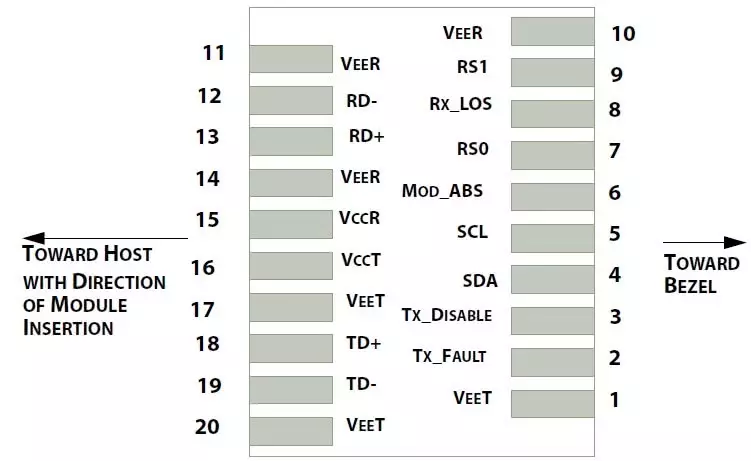
Diagram of Host Board Connector Block Pin Numbers and Name
Pin Function Definitions
| Pin | Symbol | Name/Description | NOTE |
| 1 | VEET | Transmitter Ground (Common with Receiver Ground) | 1 |
| 2 | TFAULT | Transmitter Fault. | 2 |
| 3 | TDIS | Transmitter Disable. Laser output disabled on high or open. | 3 |
| 4 | SDA | 2-wire Serial Interface Data Line | 4 |
| 5 | SCL | 2-wire Serial Interface Clock Line | 4 |
| 6 | MOD_ABS | Module Absent. Grounded within the module | 4 |
| 7 | RS0 | Rate Select 0 | 5 |
| 8 | LOS | Loss of Signal indication. Logic 0 indicates normal operation. | 6 |
| 9 | RS1 | No connection required | 1 |
| 10 | VEER | Receiver Ground (Common with Transmitter Ground) | 1 |
| 11 | VEER | Receiver Ground (Common with Transmitter Ground) | 1 |
| 12 | RD- | Receiver Inverted DATA out. AC Coupled | |
| 13 | RD+ | Receiver Non-inverted DATA out. AC Coupled | |
| 14 | VEER | Receiver Ground (Common with Transmitter Ground) | 1 |
| 15 | VCCR | Receiver Power Supply | |
| 16 | VCCT | Transmitter Power Supply | |
| 17 | VEET | Transmitter Ground (Common with Receiver Ground) | 1 |
| 18 | TD+ | Transmitter Non-Inverted DATA in. AC Coupled. | |
| 19 | TD- | Transmitter Inverted DATA in. AC Coupled. | |
| 20 | VEET | Transmitter Ground (Common with Receiver Ground) | 1 |
Notes:
- Circuit ground is internally isolated from chassis ground.
- TFAULTis an open collector/drain output, which should be pulled up with a 4.7k – 10k Ohms resistor on the host board if intended for use. Pull up voltage should be between 2.0V to Vcc + 0.3V.A high output indicates a transmitter fault caused by either the TX bias current or the TX output power exceeding the preset alarm threshold. A low output indicates normal operation. In the low state, the output is pulled to <0.8V.
- Laser output disabled on TDIS>2.0V or open, enabled on TDIS <0.8V.
- Should be pulled up with 4.7kΩ- 10kΩ host board to a voltage between 2.0V and 3.6V. MOD_ABS pulls line low to indicate module is plugged in.
- Internally pulled down per SFF-8431 Rev 4.1.
- LOS is open collector output. It should be pulled up with 4.7kΩ – 10kΩ on host board to a voltage between 2.0V and 3.6V. Logic 0 indicates normal operation; logic 1 indicates loss of signal.
EEPROM Information and Management
The SFP+ transceivers support the 2-wire serial communication protocol as defined in the SFP MSA.
The standard SFP serial ID provides access to identification information that describes the transceiver’s capabilities, standard interfaces, manufacturer, and other information.
Additionally, The SFP+ transceivers provide a unique enhanced digital diagnostic monitoring interface, which allows real-time access to device operating parameters such as transceiver temperature, laser bias current, transmitted optical power, received optical power and transceiver supply voltage. It also defines a sophisticated system of alarm and warning flags, which alerts end-users when particular operating parameters are outside of a factory set normal range.
The SFP MSA defines a 256-byte memory map in EEPROM that is accessible over a 2-wire serial interface at the 8 bit address 1010000X (A0h).The digital diagnostic monitoring interface makes use of the 8 bit address 1010001X (A2h), so the originally defined serial ID memory map remains unchanged.
The operating and diagnostics information is monitored and reported by a Digital Diagnostics Transceiver Controller (DDTC) inside the transceiver, which is accessed through a 2-wire serial interface. When the serial protocol is activated, the serial clock signal (SCL, Mod Def 1) is generated by the host. The positive edge clocks data into the SFP transceiver into those segments of the E2PROM that are not write-protected. The negative edge clocks data from the SFP transceiver. The serial data signal (SDA, Mod Def 2) is bi-directional for serial data transfer. The host uses SDA in conjunction with SCL to mark the start and end of serial protocol activation. The memories are organized as a series of 8-bit data words that can be addressed individually or sequentially.
Table 1. Digital Diagnostic Memory Map (Specific Data Field Descriptions)
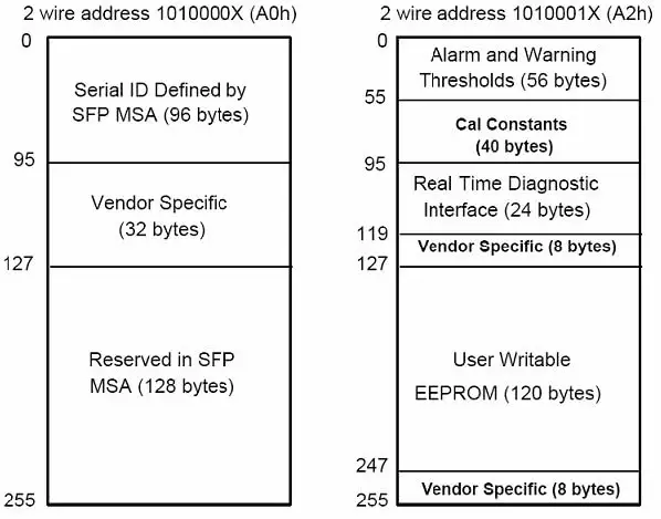
Table 2 – EEPROM Serial ID Memory Contents (A0h)
| Data Address | Length
(Byte) |
Name of
Length |
Description and Contents |
| Base ID Fields | |||
| 0 | 1 | Identifier | Type of Serial transceiver (03h=SFP) |
| 1 | 1 | Reserved | Extended identifier of type serial transceiver (04h) |
| 2 | 1 | Connector | Code of optical connector type (07=LC) |
| 3-10 | 8 | Transceiver | 10G Base-XX |
| 11 | 1 | Encoding | 64B/66B |
| 12 | 1 | BR, Nominal | Nominal baud rate, unit of 100Mbps |
| 13-14 | 2 | Reserved | (0000h) |
| 15 | 1 | Length(9um) | Link length supported for 9/125um fiber, units of 100m |
| 16 | 1 | Length(50um) | Link length supported for 50/125um fiber, units of 10m |
| 17 | 1 | Length(62.5um) | Link length supported for 62.5/125um fiber, units of 10m |
| 18 | 1 | Length(Copper) | Link length supported for copper, units of meters |
| 19 | 1 | Reserved | |
| 20-35 | 16 | Vendor Name | SFP+ vendor name |
| 36 | 1 | Reserved | |
| 37-39 | 3 | Vendor OUI | SFP+ transceiver vendor OUI ID |
| 40-55 | 16 | Vendor PN | Part Number |
| 56-59 | 4 | Vendor rev | Revision level for part number |
| 60-62 | 3 | Reserved | |
| 63 | 1 | CCID | Least significant byte of sum of data in address 0-62 |
| Extended ID Fields | |||
| 64-65 | 2 | Option | Indicates which optical SFP signals are implemented(001Ah = LOS, TX_FAULT, TX_DISABLE all supported) |
| 66 | 1 | BR, max | Upper bit rate margin, units of % |
| 67 | 1 | BR, min | Lower bit rate margin, units of % |
| 68-83 | 16 | Vendor SN | Serial number (ASCII) |
| 84-91 | 8 | Date code | Manufacturing date code |
| 92-94 | 3 | Reserved | |
| 95 | 1 | CCEX | Check code for the extended ID Fields (addresses 64 to 94) |
| Vendor Specific ID Fields | |||
| 96-127 | 32 | Readable | specific date, read only |
| 128-255 | 128 | Reserved | Reserved for SFF-8079 |
Digital Diagnostic Monitor Characteristics
| Data Address | Parameter | Accuracy | Unit |
| 96-97 | Transceiver Internal Temperature | ±3.0 | °C |
| 98-99 | VCC3 Internal Supply Voltage | ±3.0 | % |
| 100-101 | Laser Bias Current | ±10 | % |
| 102-103 | Tx Output Power | ±3.0 | dB |
| 104-105 | Rx Input Power | ±3.0 | dB |
Regulatory Compliance
The SFP+ complies with international Electromagnetic Compatibility (EMC) and international safety requirements and standards (see details in Table following).
| Feature | Reference | Performance |
| Electrostatic discharge(ESD) | IEC/EN 61000-4-2 | Compatible with standards |
| Electromagnetic Interference (EMI) | FCC Part 15 Class B EN 55022 Class B (CISPR 22A) | Compatible with standards |
| Laser Eye Safety | FDA 21CFR 1040.10, 1040.11 IEC/EN 60825-1, 2 | Class 1 laser product |
| Component Recognition | IEC/EN 60950, UL | Compatible with standards |
| ROHS | 2002/95/EC | Compatible with standards |
| EMC | EN61000-3 | Compatible with standards |
Recommended Circuit
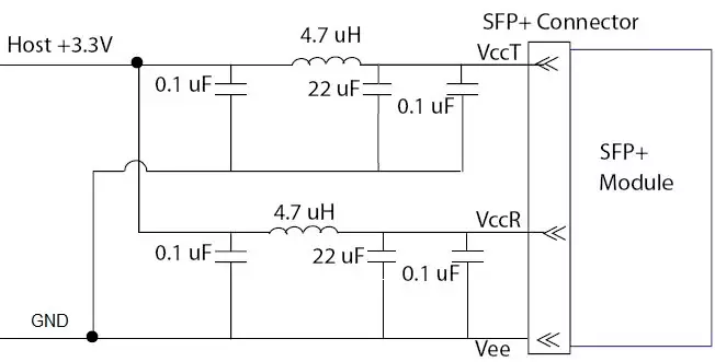
Recommended Host Board Power Supply Circuit
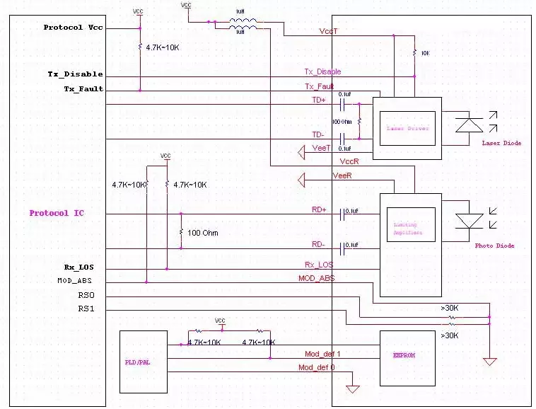
Host – Transceiver Interface Block Diagram
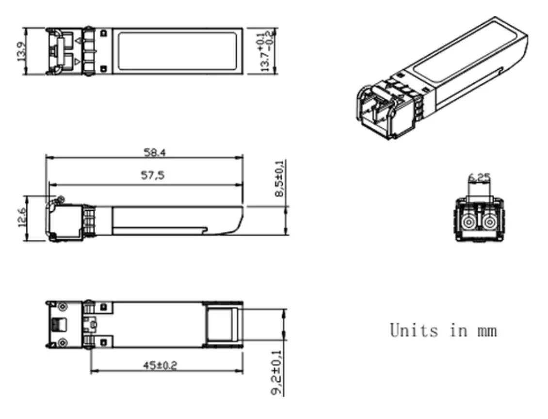
Outline Dimensions
Comply to SFF-8432 rev. 5.0, the improved Pluggable form factor specification.
Reviews
There are no reviews yet.