Fiber optic cables and networking have a lot of different terms and designs. Some people might ask what is LC/UPC | LC/UPC? What is SC/APC | SC/APC? UPC and APC are two polish types / grinding methods for optical fiber bushings.
UPC vs APC ?
Install connectors on one fiber end face, return loss is unavoidable, this is due to the reflection of the optical source. Serious optical loss will damage the laser optical source and interrupts the transmission of signals. Therefore, connector rings with different grinding methods can avoid severe echo loss to a certain extent. UPC and APC are two widely used grinding types.
Differences Between UPC and APC Connector
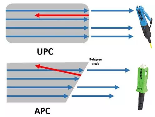
The main difference between UPC and APC connector is the fiber end face. UPC connectors are polished with no angle, but APC connectors feature a fiber end face that is polished at an 8-degree angle. With UPC connectors, any reflected light is reflected straight back towards the light source. However, the angled end face of the APC connector causes reflected light to reflect at an angle into the cladding versus straight back toward the source. This causes some differences in return loss.
Therefore, UPC connector is usually required to have at least -50dB return loss or higher, while APC connector return loss should be -60dB or higher. In general, the higher the return loss the better the performance of the mating of two connectors. Besides the fiber end face, another more obvious difference is the color.
Generally, UPC connectors are BLUE while APC connectors are GREEN. The following figure picture shows the differences mentioned above intuitively.
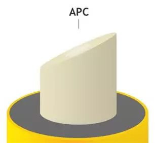
APC, angular physical contact. The end face is drawn to a 8 degree angle, which is beveled to reduce reflection. APC can only be connected to APC. Since the structure of the APC is completely different from the UPC, if the two connectors are connected with a flange, the optical fiber end of the connector will be damaged.
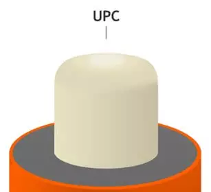
UPC, ultra physical contact, evolved from PC and has better surface finish. UPC connector depends on machine polishing, low return loss.
UPC and PC connectors are generally used in Ethernet network equipment like fiber switch, and are compatible with most standard fiber SFP modules. Instead, APC connectors are mostly employed in PON network architecture or passive optical LANs, and they are not recommended to be used with fiber SFP modules. Therefore, choose the right connector depends on your particular networking needs.


Some example of APC & UPC Fiber Cables listed below
150M Duplex Single Mode LC-LC UPC Fiber Cable | Fiber Drop Cable | Outdoor Cable
30M Simplex Single Mode UPC LC-LC Fiber Optic Cable | Fiber Patch Cord | Outdoor Drop Cable
3 Meter Simplex SC to SC Fiber Flylead Cable 3mm, Single Mode 9/125um Patch Cord (FTTH)
Fiber SFP Module Compatibility with APC & UPC
Most optical transceiver modules have two ports for bidirectional communication except for BiDi SFP Modules that uses a single optical cable for transmitting and receiving signals. For a Complete list of SFP Speeds and designs please see the wiki at Small Form Factor Pluggable Transceiver
G652D vs G657A Fiber Cable Specifications and Differences
G652D and G657A2 specifications refer to the glass and cable construction of optical fibre and are generally the fibres of choice in optical fibre patch leads for singlemode systems.
ITU-T G652D singlemode fibres have been used in all networks for more than 30 years. Being backwards compatible, this makes for easier maintenance/repair (splicing fibres of the same type). The G652D fibre Mode Field Diameter is 10.4µm @1550nm.
G652D fibres provide marginally lower loss transmission, which is better in facilitating long distance communication links (up to and greater than 100km).
However, G652D fibres have limited bend resistance.
G657A2 fibres are used in advanced access cable network installation, where higher bend resistance is required for smaller cable jointing pits and also allows for cable and hardware miniaturisation.
G657A2 fibres are fully compatible with G652D fibres. The G657A2 fibre Mode Field Diameter is 9.8µm@1550nm. Splice losses are slightly higher when splicing the two different fibres together.
G657A2 fibre has greater resistance to bending (macrobend) losses (see figure below), and facilitating low-cost deployment techniques.
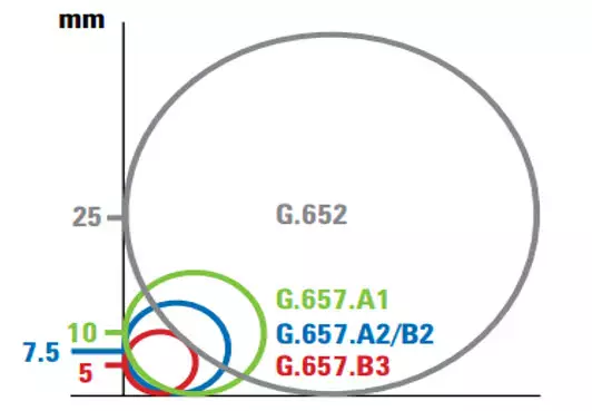
Figure1: Relevant Bending radii for G652 and G657 fibres.
- Fibre Bending Radii Vs Attenuation Increase at 1550nm.
| Fibre Type | Bending Radii | Attenuation Increase (db) |
| G652D | 100 turns on 25mm mandrel at 1310/1550nm | ≤ 0.03 |
| G652D | 100 turns on 30mm mandrel at 1625nm | ≤ 0.1 |
| G657A2 | 10 turns on 15mm mandrel at 1550nm | ≤ 0.05 |
| G657A2 | 10 turns on 15mm mandrel at 1625nm | ≤ 0.1 |
| G657A2 | 1 turn on 10mm mandrel at 1550nm | ≤ 0.1 |
| G657A2 | 1 turn on 10mm mandrel at 1625nm | ≤ 0.2 |
| G657A2 | 1 turn on 7.5mm mandrel at 1550nm | ≤ 0.5 |
| G657A2 | 1 turn on 7.5mm mandrel at 1625nm | ≤ 1.0 |
Advantages:
G652D Marginally lower attenuation and lower splicing losses, when splicing like fibres. Providing longer cable networks.
G657A2 Smaller cable and cords installation radii, providing for low-cost installation, miniaturisation and higher density connectorization.
Therefore, G657A2 optical fibre in patch cords, provide an improved bend radius and flexibility, which may allow for better cable management and routing in congested areas. The improved bend radius may also allow for increased density in high-density patching fields. G657A2 optical fibre is becoming very popular in the Data Centre and Enterprise network deployments.
What Is a BiDi SFP?
Bidirectional SFP can be defined as a compact, hot swappable, input/output optical module with LC/SC connector that can transmit and receive data to/from interconnected equipment through a single optical fiber. Unlike traditional optical transceivers, BiDi optical transceivers are fitted with wavelength division multiplexing (WDM) diplexers, which combine and separate data transmitted over a single fiber based on the wavelengths of the light. For this reason, BiDi transceivers are also referred to as WDM transceivers.
Example of a Bidi SFP Network Installation
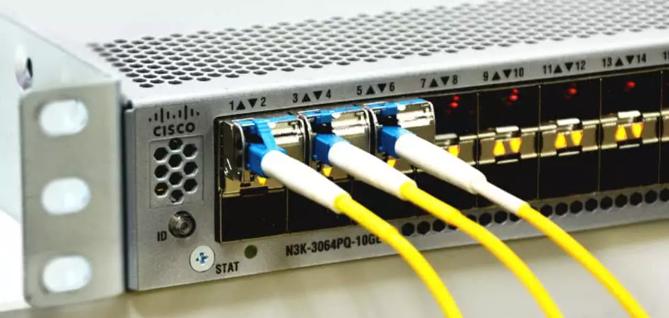
In Dual Cable SFP’s one port is used for sending signals and the other one is for receiving signals. Normally, this transmission process is achieved through a fiber patch cable. Fiber patch cables are designed with different connectors, like SC APC, LC UPC etc. It is important to check whether the fiber connectors are compatible with the SFP optical transceivers before making the connection. Otherwise, it will cause serious consequences such as invalid connection or network failure. For example, we can not use Fiber Cables with APC connector in SFP modules. Because the APC connector has an angle, but the connector of the SFP module is flat. Therefore, misalignment will be created when pairing APC and a SFP module, which will result in more loss and even the interface within the transceiver may be damaged.
Examples of BiDi SFP Transceiver Modules with applicable Network Switches below
3km Single Mode Bi-Directional SFP Transceiver Module SET | Cisco & Generic Switch Compatible
10 Port SFP Gigabit Fiber Media Converter with 8xSFP 1.25Gbps Ports & 2 x Gigabit RJ45 Network Ports
Gigabit Fiber Media Converter | 1Gbps RJ45 Ethernet to 1000Base-FX SFP | Fiber to Ethernet
Example of a Dual LC Fiber Cable Installation with Network Fiber SFP
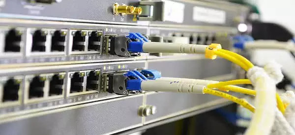
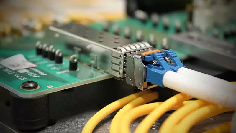
Examples of Dual LC SFP’s and Applicable Network Switches below
6 Port Gigabit POE Network Switch with SFP Port & RJ45 Uplink Port
APC vs UPC vs PC, Choose the Correct One For a Fiber SFP Module
In principle, different connectors can not be paired. However, the fiber ends of PC and UPC are flat, and the difference between them is the quality of polishing. Therefore, UPC and PC are compatible and interchangeable without causing any damages to the connectors. This means UPC or PC fiber can be equally used with fiber SFP module.
However, the physical and mechanical properties of APC connector are quite different. This means APC should not be paired with UPC or PC. If someone does that, it will destroy the connectors. It is not recommended to use APC connectors in fiber SFP modules. Unless the transceiver module has stated clearly that the APC connectors are allowed, users may use UPC connectors. If the network requires a connection between a fiber SFP module and an APC connector, users must use a conversion patch cable (UPC to APC) to connect from a transceiver with flat UPC/PC interface to an angled APC interface.
What is the difference between multimode and single mode fiber optic cables?
Single mode cables are designed to carry light directly down the fiber. It is a single strand of glass fiber and has a diameter of 8.5-10 microns. Because it has one mode of transmission, it will propagate 1310 or 1550 nm.
Compared to the multimode fiber, the single mode patch cords carry a higher bandwidth, but it requires a light source with a narrow spectral width. The single mode gives a higher transmission and up to 50 times more distance than the multimode. The core from a single mode cable is smaller than one from a multimode.
Single mode is a vital part of broadband networks. It designed to transmit data over long distances, thus making it perfect for cable television networks / fiber optic IP Networks over great distances.
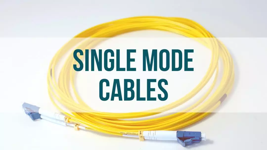
Examples of Single Mode Cables Below
1M Duplex Single Mode UPC LC-LC Fiber Cable | Fiber Optic Patch Cord
Multimode patch cords have a bigger diameter, typically 50-100 microns for the light carry component. Over medium distances, multimode fibers give high bandwidths at high speeds. Light waves are dispersed into numerous paths, or modes, as they travel through the cable’s core typically 850 or 1300nm.
In cable runs longer than 914,4 meters, the multiple cable pats can cause distortion at the receiving end, resulting in an unclear and partial data transmission.
Multimode cables are considered to be the “domestic” fiber as they are used for local-area network, as an example, they can be used in FTTH. Multimode can reach up to 100Gbps Ethernet.
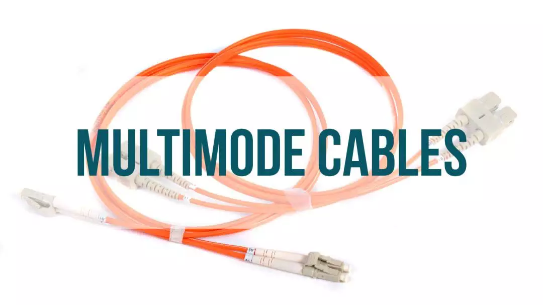
Examples of Multi Mode Cables Below
1M Duplex MultiMode OM3 Fiber Cable | UPC LC-LC Fiber Cable | Fiber Patch Cord
Single Mode SFP vs Multimode SFP: What’s the Difference?
SFP transceiver module, also known as small form-factor plug-gable or mini GBIC, is a hot-plug-gable optical transceiver module which is commonly used for both telecommunication and data communications applications. According to the cable type it used together with, SFP transceivers are divided into single mode SFP and multimode SFP. Single mode SFP works with single mode fiber, while multimode SFP works with multimode fiber.
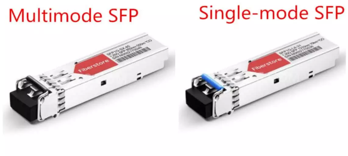
Single Mode SFP vs Multimode SFP: What’s the Difference?
There are several main differences between single mode SFP and multimode SFP:
Single Mode SFP vs Multimode SFP: Working Wavelength
Single mode SFP module has a narrower laser wavelength, which works mainly in 1310nm and 1550nm wavelength. Whereas multimode SFP module works in 850nm wavelength due to the larger core size.
Single Mode SFP vs Multimode SFP: Color Coding
The color coded bale clasp and color arrow of single mode SFP modules are generally designed in blue, yellow or purple. Blue is the 1310nm module, yellow is the 1550nm module and purple is the 1490nm module. And the color of compatible fiber optic patch cord is yellow.
While the color coded bale clasp and color arrow on the label of multimode SFP modules are black and the used fiber optic patch cord is usually orange.
Single Mode SFP vs Multimode SFP: Transmitter
Single mode SFP and multimode sfp use different types of transmitters. VCSELs are typically used in multimode SFP transceivers. They can be tested on the wafer level and don’t need a hermetic package. Edge-emitting lasers, such as Fabry–Pérot, DFB and DBR lasers, are utilized in single mode SFP modules for different reaches and applications. They have complex layer structures and often require a hermetic package to achieve higher emission power and stable single mode operation. Therefore, Edge-emitting lasers are more costly than VCSELs.
Planning for the Future
Industry standards groups including IEEE (Ethernet), INCITS (Fibre Channel), TIA, ISO/IEC and others continue to include multimode optical fiber as the short reach solution for next generation speeds. This designation reinforces multimode optical fiber’s continued economic advantage for these applications.
For Longer Distances Single Mode fiber is commonly installed since Multi-Mode Distances are much less than Single Mode Fiber.
IEEE includes multimode optical fiber in its 40G and 100G Ethernet standards as well as its pending 50G, 200G, and 400G standards. In addition, TIA issued a new standard for the next generation of multimode optical fiber called wide band (OM5) multimode optical fiber. This new version of 50 µm optical fiber can transmit multiple wavelengths using Short Wavelength Division Multiplexing (SWDM) technology, while maintaining OM4 backward compatibility. In this way, end users can obtain greater bandwidth and higher speeds from a single fiber by simply adding wavelengths.